Where Is the Shift Interlock Solenoid on a 2000 Mercury Villager
Mercury Villager 1st Generation (1993 – 1998) – fuse box diagram
Year of production: 1993, 1994, 1995, 1996, 1997, 1998
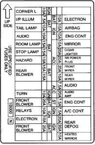
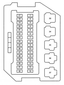
Fuse box in instrument panel


| № | Fuse | A | Description |
| 1 | Open | — | Not Used |
| 2 | Electron | 10 | A/C (Air Conditioning), Timer Module |
| 3 | Airbag | 10 | Air Bag |
| 4 | Engine Cont | 10 | Engine Emissions, Evaporative Emissions, Powertrain Control Module (PCM) |
| 5 | Mirror | 10 | Power Mirror, Timer Module |
| 6 | Cigar Lighter | 20 | Cigar Lighter |
| 7 | Rear Power Plug | 20 | Rear Power Plug |
| 8 | Front Wiper | 20 | Front Windshield Wiper/Washer |
| 9 | Rear Wiper | 10 | Rear Window Wiper/Washer |
| 10 | Audio | 7.5 | Radio, Power Antenna, Rear Integrated Control Panel (RICP) |
| 11 | Audio Amp | 20 | Subwoofer Amplifier |
| 12 | Electron | 7.5 | Powertrain Control Module (PCM) |
| 13 | A/C Cont | 7.5 | A/C, Auto Light, Rear Defrost Switch |
| 14 | Rear Defog | 20 | Rear Defrost |
| 15 | Rear Defog | 20 | Rear Defrost |
| 16 | Heated Mirror | 10 | Heated Power Outside Side View Mirrors |
| 17 | Corner L | 10 | Cornering Lamp |
| 18 | I/P Ilum | 7.5 | Instrument Illumination, Radio Illumination |
| 19 | Tail Lamp | 10 | Tail Lamp, Rear Parking Lights |
| 20 | Audio | 10 | CD, Power Antenna, Radio |
| 21 | Room Lamp | 15 | Dome Lamps, Step Lamps, Warning Chime |
| 22 | Stop Lamp | 15 | Shift-Lock Solenoid, Stoplamps |
| 23 | Hazard | 10 | Hazard Flasher |
| 24 | Rear Blower | 15 | Rear Blower Motor |
| 25 | Rear Blower | 15 | Rear Blower Motor |
| 26 | Open | — | Not Used |
| 27 | Turn | 10 | Turn Signal Lamps |
| 28 | Front Blower | 20 | Front Blower Motor |
| 29 | Relays | 10 | Relays in Main Fuse Junction Panel |
| 30 | Electron | 10 | Anti-lock Brakes (ABS), Backup Lamps, Overdrive Off Lamp, PRND Switch |
| 31 | Front Blower | 20 | Front Blower Motor |
| 32 | Open | — | Not Used |
| Relay | |||
| 33 | Accessory #1 | Fuses 17,18,19 | |
| 34 | Ignition | Fuses 26, 27, 29, 30 | |
| 35 | Accessory #2 | Fuses 5, 6, 7,8,9 | |
| 36 | Rear Defrost | Fuses 14,15,16 | |
| 37 | Blower | Fuses 28, 31 | |
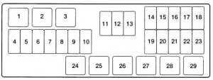
Engine compartment main fuse panel

| № | Fuse | A | Description |
| 4 | POWER WINDOW | 30 | Power Seat, Power Window, Sun Roof |
| 5 | ABS | 30 | Anti-lock Brake Control Module |
| 6 | RAD FAN | 65 | Cooling Fan |
| 7 | FRONT BLOWER | 65 | Front Blower Motor |
| 8 | MAIN | 100 | Hazard Lamps, Interior Illumination, Radio, Stoplamps, Transmission Control Module |
| 9 | ALT | 120 | Mini Fuse Portion of Main Fuse Junction Panel |
| 10 | RRDEF | 45 | Heated Mirrors, Heated Rear Window, Rear Blower Motor |
| 11 | IGNSW | 30 | Ignition Switch |
| 12 | OPEN | — | Not Used |
| 13 | OPEN | — | Not Used |
| 14 | H/LRH | 15 | Right-Hand Headlamp |
| 15 | H/LLH | 15 | Left-Hand Headlamp |
| 16 | ALT | 10 | Alternator Input |
| 17 | ENG CONT | 10 | Powertrain Control Module (PCM) Relay |
| 18 | INJ | 10 | Fuel Injectors |
| 19 | FUEL PUMP | 15 | Fuel Pump Relay |
| 20 | HORN | 15 | Horn Relay |
| 21 | ABS | 20 | Anti-lock Brake Hydraulic Actuator |
| 22 | HOODLAMP/ TRLRTOW | — | Hood Lamp/Trailer Tow |
| 23 | S.E.C. | 7.5 | Keyless Entry Beeper, Timer Module |
| Relay | |||
| 1 | RAD FAN LO | Cooling Fan (Low Speed) | |
| 2 | RADFAN HI 1 | Cooling Fan (Medium Speed) | |
| 3 | RADFAN HI 2 | Cooling Fan (High Speed) | |
| 24 | HORN | High Horn, Low Horn | |
| 25 | FUEL PUMP | Fuel Pump | |
| 26 | INHIBIT | Starter Motor | |
| 27 | HEADLAMP RH | Right-Hand Headlamp | |
| 28 | BULB CHECK | Brake Warning Lamp, Charge Warning Lamp | |
| 29 | ASCD HOLD | Speed Control Module | |
Relay box

| № | Description |
| 1 | Antitheft (Interrupt) (If equipped) |
| 2 | Headlamp LH |
| 3 | Blank |
| 4 | FICD |
| 5 | Auto Light Headlamp/Antitheft Headlamp |
| 6 | Air Conditioner |
WARNING: Terminal and harness assignments for individual connectors will vary depending on vehicle equipment level, model, and market
Where Is the Shift Interlock Solenoid on a 2000 Mercury Villager
Source: https://www.autogenius.info/mercury-villager-1st-generation-1993-1998-fuse-box-diagram/
0 Response to "Where Is the Shift Interlock Solenoid on a 2000 Mercury Villager"
Postar um comentário